
Electric Manual Vent Butterfly Valve
Electric Manual Vent Butterfly Valve
1. Overview
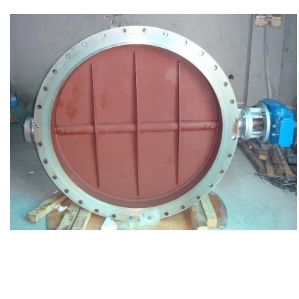
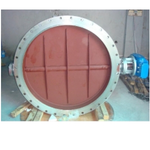
The ventilation butterfly valve is a control device that can be operated manually or by motor drive. It allows the disc to rotate freely within a 90° range, enabling the opening, closing, or adjustment of medium flow. This valve finds wide applications in industries such as chemical, building materials, power stations, and glass for controlling gas flow in pipelines used for environmental protection engineering dust containing cold or hot air.
2. Structural Features
1) It is designed and manufactured using a new structural welding method between the central line plate and the short structure steel plate. This design offers advantages such as compactness, light weight, easy installation, minimal flow resistance, high circulation capacity, and resilience to temperature expansion effects.
2) Without connecting rods or bolts, it ensures reliable operation and long service life. It can be installed at multiple stations without being affected by media flow.
3) The ventilated butterfly valve is constructed through steel plate welding with characteristics including a compact size, lightweight construction, and ease of installation. It effectively controls or adjusts gaseous mediums while featuring a large expansion gap between the butterfly plate and valve body to prevent jamming due to thermal expansion or contraction.
4) The valve can be equipped with various driving devices such as manual mechanisms, worm gear transmission systems, pneumatic devices, or electric actuators for ventilation butterfly valves.
3. The installation points are as follows:
1) The installation position, height, inlet and outlet direction must meet the design requirements. Pay attention to ensuring that the medium flow direction aligns with the arrow marked on the valve body. Additionally, ensure firm and secure connections.
2) Prior to installation, valves must undergo inspection to ensure compliance with the national standard “General Valve Mark” GB 12220. Valves with a working pressure greater than 1.0MPa and serving as shut-off devices on main pipelines should undergo strength and tightness tests before use. During the strength test, apply a test pressure of 1.5 times the nominal pressure for a duration of not less than 5 minutes, ensuring no leakage from the valve shell or packing is present when qualified. For tightness testing, apply a test pressure of 1.1 times the nominal pressure; meeting GB 50243 requirements for test duration.
Leave a Reply